About the Bella Street Pumphouse
One of the most important developments on the Thames Goldfield during the 1890’s was the formation of the Thames-Hauraki Goldfields Company which acquired the old Queen of Beauty mine and adjacent properties-a total of 101ha.Their aim was to erect machinery capable of winding and pumping to a depth of 610m. In the first instance, they planned to sink the old Queen of Beauty shaft to 305m.
The following will give you a brief glimpse of what was involved in achieving the first stage of this objective. Circumstances did not allow the second stage, the sinking to 610m, to eventuate.
Queen of Beauty Shaft
During 1896, the company widened the Queen of Beauty shaft to a depth of 130m. The dimensions were 5.3 x 2.6m. It was timbered with frames 40 x 30 cm heart kauri. These frames were 1.2m apart with 40cm studdles in the corners and lagged behind with 50mm thick planking. At 91m, the shaft was widened out to 5.3m x 5.0m to provide space for the change of lifts which occurred every 99m. At the northern end of the shaft was a 2.6 x 1.4m division for the winding cages.
By March 31st 1899, the shaft had been enlarged to a depth of 161.5m, the old Queen of Beauty No. 8 Level. At a depth of 181.3m, the shaft was enlarged for a vertical distance of 12.2m to 7.6 x 6.0m overall to provide a chamber for the second set of plunger gear. A year later, the shaft was down to 228.6m, at which level, the bottom of the old Queen of Beauty shaft was reached. From that point on to the proposed depth of 305m, it was solid ground.In September 1900, a dispute arose between the May Queen Company and the Thames –Hauraki Company over the contributions to be paid and the depth at which the water was to be kept in the shaft. Sinking was suspended and the water allowed to rise to 46m above the bottom of the shaft. The May Queen Goldmining Company sunk the shaft to 311m in 1909. They were able to carry out this very expensive work through a government subsidy (pound for pound) and assistance from the Thames Borough and County Councils. Once the shaft attained this depth, and the chamber constructed, the permanent draw lifts were installed. The work was completed in June. During 1910, the Thames Deep Level Scheme commenced a northerly crosscut from the 305m level of this shaft.
Structures-Foundations
Foundations: After carefully testing the ground by pile-driving, the site for the foundations for the new pump engine was fixed on the west side of the shaft. The area was 21.3 x 20.7m, and within this area, forty piles 30cm square, were driven. They were then cut 1.2m above the ground and the whole area bound together by a 60cm layer of concrete.
On this smooth surface, boxes laid in various directions, were of sufficient size to allow a man to enter. Upon these, sixtyfour perpendicular boxes, 15 x 10cm and 5.5m long were placed. These were stayed and braced to keep them in position so that the holding down bolts from the engine bed could be placed in position and secured below. Concrete was then poured to a depth of 5.5m securing these boxes and was extended on the east and west side of the shaft to a depth of 3.6m for the support of the pump quadrants.
On three sides of the shaft, there was this one massive concrete block weighting approximately 6000 tons. As this was required to carry such heavy machinery, it was decided by the Government Inspector and the manager for the company, that only the best Portland cement be used in its construction. One part of cement to five parts of gravel and broken metal was used.
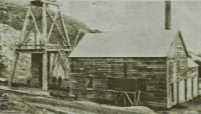
Boiler House and Stoke Hole. This building is 30.5 x 22.9m with a 6.0m stud. The greater width allowed storage for about 250 tons of coal. 7467m of first class kauri valued at $3.00 per 30.5m was used in its construction. The building was clad in corrugated iron.
Pumping Building. This building is 32.3 x 22.9m with a 8.55m stud. It is detached from the boiler house. It was estimated there were 6553m of first class kauri used in its construction. Like the boiler house, it is clad in corrugated iron.
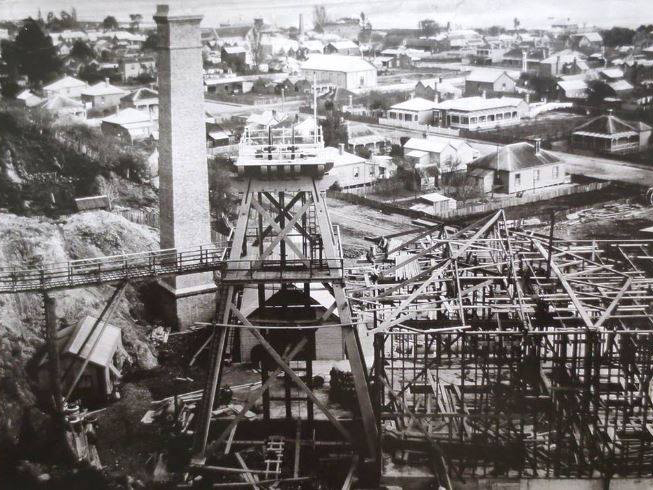
Construction of the pump building.
Smoke Stack. The stack rose to a height of 32.6m being 4.0m square at the base and 2.7m square at the top.
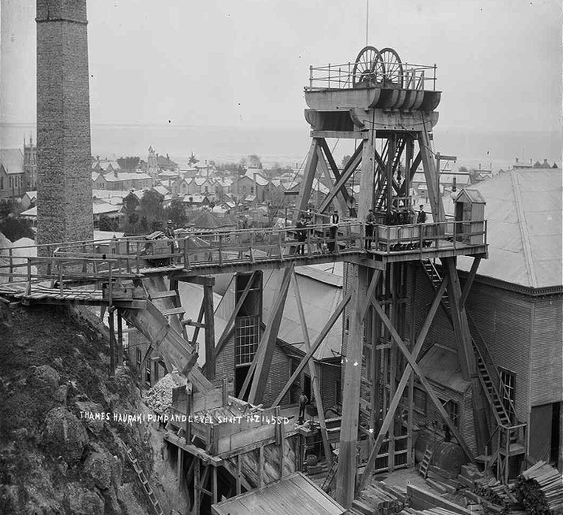
Poppet Head
The four legs of the poppet head were made of kauri. They were approximately 19.8m long measuring 76cm at the base and tapering to 45cm at the top. Each leg was set in sole pieces and were firmly embedded in concrete. The whole structure was firmly braced together. On top were two sheave wheels 2.7m in diameter. The whole structure was capable of bearing a transverse working strain of 400 tons. (Fundraising is currently under way to build a replica poppet head.)
Boilers
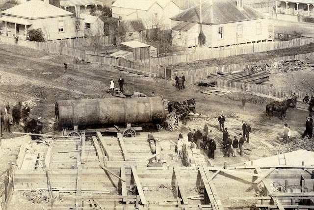
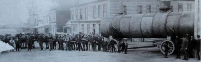 A boiler leaving Prices for the Thames Hauraki Pump building.
Ten steel Lancashire boilers, 9.1m long and 2.1m in diameter, were assembled and riveted together by Messrs Price Brothers of Thames. Each boiler was tested up to a hydraulic pressure of 300 lbs per sq. in. before leaving Prices establishment. The boilers were transported through Thames by horse and wagon from the foundry to the plant, set in position and fitted with Howl’s patent furnaces for burning coal.
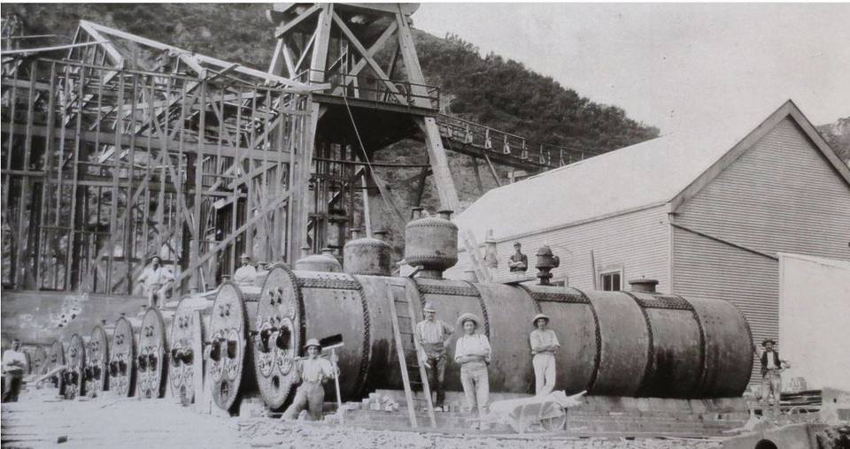
10 boilers in place on site ready for installation.
The Howl’s furnaces, which were fitted into the internal flues of these boilers, produced a greater saving in the consumption of fuel. Everything had to burn to ashes sufficiently small enough to come through a hole or slot measuring 4mm wide.
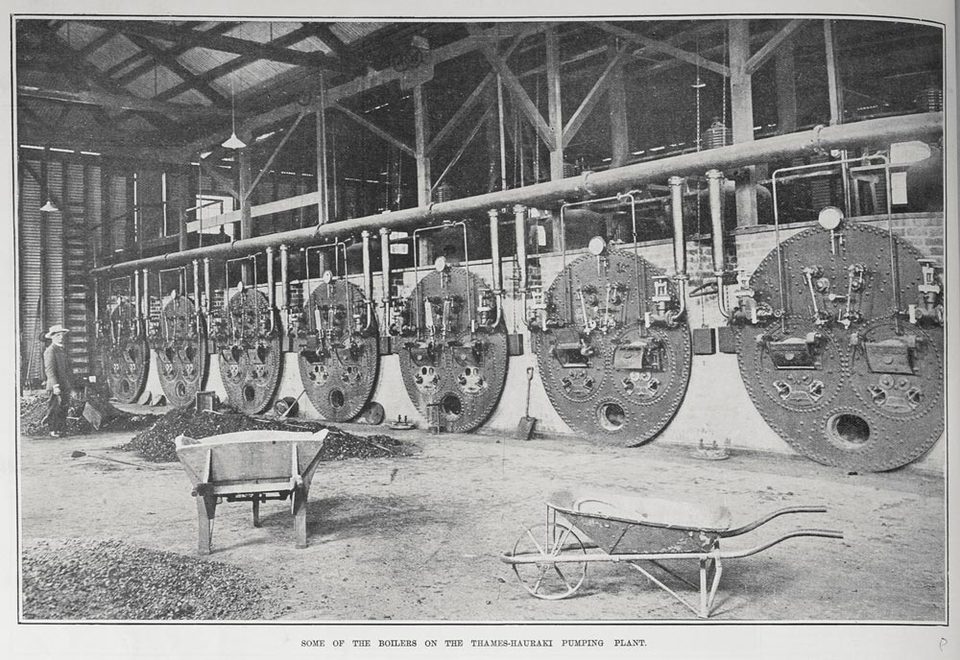
Boilers installed in the boiler house at the Thames Hauraki pump.
The principle of these patent furnaces was that the fuel was charged onto plates having narrow slots instead of fire-bars and there, a jet of steam from the boiler was introduced underneath the plates. The steam, passing through the hot fire, was relieved of its oxygen thus the hydrogen was set free and burnt. This jet not only carried a draught, but increased the heat of the flame from the fuel. The flame, after passing through the internal tubes, passed into the flue underneath the boilers and returned to the flues at each side. The back end of each side flue was fitted with a damper to regulate the draught in each boiler. Steam of 120 p.s.i. was generated for the pumping engines and other machinery. The boilers were set side by side having flues on the side and underneath. These led to a large flue 94cm wide and 2.1m high which went along the back end of the row of boilers and led to the chimney stack. In front of the boilers, the concrete floor held up to 250 tons of coal.
Winding and Capstan Machinery
The foundations for the winding engine were 4.6m long, 44.6m wide and 2.9m thick. In front and 1.2m below was the capstan winding engine foundation measuring 6.9m long, 3.3m wide and 2.1m thick. Both of these engines were housed in the same building.
The winding drums were 1.8m in diameter and fitted with a clutch and reversing gear. The rope was steel wire 29mm in diameter. This was used for raising lowering the two mine cages. The capstan engine weighed 29 tons and was fitted with a 50mm diameter wire rope capable of lifting 25 tons. It was used for raising and lowering the heavy parts of the pumping machinery in the shaft.
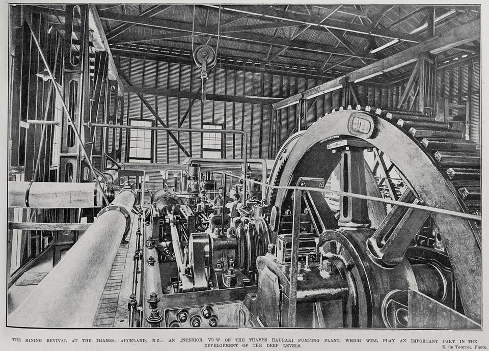
Pumping Machinery
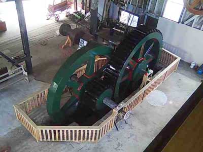 The engine consisted of a pair of compound condensing engines. The high pressure cylinder was 76cm in diameter and the low pressure 1.5m. both having a 1.5m stroke. The engine crank shaft was geared to the pump crank shaft, so that their relative speeds were a ratio of 4:1. The spur wheel on the pumping crank shaft weighed 40 tons while the weight of the engine flywheel was 30 tons. The 55cm diameter crank shaft, carrying the spur wheel, weighed 23 tons. The crank had a 1.8m stroke. The power was transmitted from this crank to the nearest pump quadrant by a rod, 6.7m long.
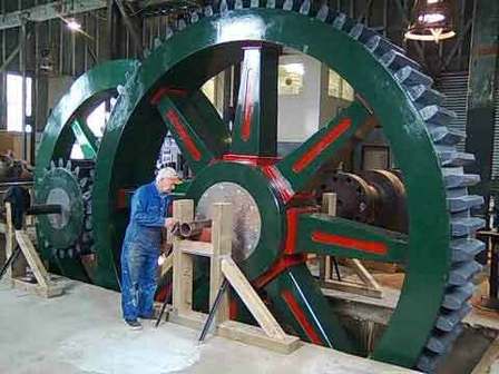
The pumps consisted of two pairs of 63.5cm plungers and one pair of 63.5cm draw lifts with a stroke of 1.8m. 82.3m below the surface, an excavation was cut east-west of the shaft for the balance bobs and counterweighs. The first pair of plungers were at 99m. 183m below the surface were a set of side levers or bobs. At 193/198m were a second set of plungers. The water was lifted 106.7m from the sump at 305m to the first cistern at 198m. The second lift was to the next cistern at 99m while the final lift brought the water to the surface where it was discharged ending up in the Firth of Thames.
Quadrants
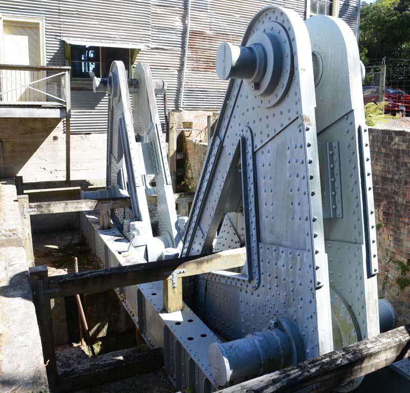
The quadrants.
These are two of only three pieces of machinery to survive (the other was the crank shaft). They are made of wrought iron, shipped from England, and strongly riveted together at A & G Price in Thames. Each quadrant weighs 22 tons and they moved all the pump gear in the shaft. The tops of the two quadrants were connected by means of a link, built of steel plate, 7.0m centre to centre. Each quadrant rocked in a pair of pillow blocks bolted down on two parallel wrought iron girders 12.2m long by 84cm thick.
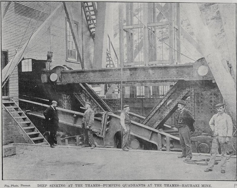
Deep sinking at the Thames-Pumping quadrants at the Thames-Hauraki mine. Auckland Weekly News 04 November 1898, p2. Auckland Libraries Heritage Collections AWNS-18981104-2-2
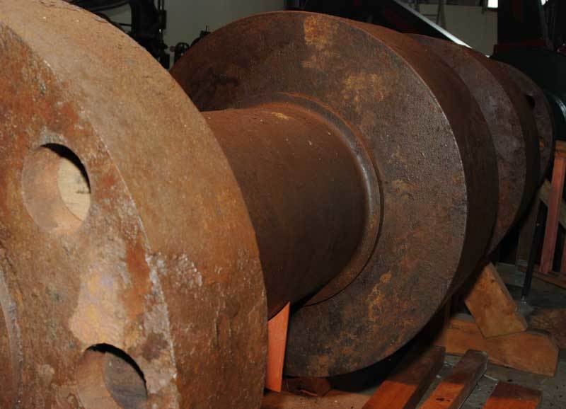
The crank shaft.
Closure and Dismantling
The machinery remained in place from the closure of the pumphouse in October 1914 until 1918 when the Mines Department decided to sell all of the plant. It then became the responsibility of the Inspector of Mines to draw up an inventory of all machinery, buildings, surface and underground equipment.
The first stage involved lifting of approximately 183m of 125mm steel pump rods from the main shaft. The rods were 8.5m long and weighed about two tons each. Attached to the bottom of these rods were brass buckets each weighing about one ton. The operation involved getting up steam in some of the boilers but due to the long period of idleness, dampness in the flues created many problems. After three days, sufficient steam was raised to work the capstan engine and one length was lifted to the surface. Due to the difficulty in breaking the joints, it was arranged with Messrs Price Bros. to have them obtain the most powerful blowlamp to help alleviate this problem. By June, 183m had been removed, but due to the long period of immersion in water, the couplings had to be freed using gelignite.
Offer-Counter Offer
A & G Price offered $930.00 for a Compound Horizontal Steam Engine. The Under Secretary of Mines replied that the department was not prepared to accept this offer but would agree to sell the engine to Messrs Price Bros. for $1000.00. Charles Judd made an offer of $1300.00 for the same engine, but the department was not prepared to accept this price either. Tenders were again called for this engine, plus additional smaller items. Four offers were received, including a fresh one from Chas. Judd Ltd. It was eventually sold to an Auckland company for $2600.00.
Today the buildings are under the care of the Bella Street Pumphouse Society Inc.
Note. All measurements and values are converted to metrics as close possible to the original imperial.
Acknowledgments
Mines Department Correspondence. Mines Statements, 1897-1914.
Private Papers-Reports.
Thames Goldfield Diamond Jubilee 1867-1927.
The Thames Star 1986-1914.
The Thames-Hauraki Pumping Plant at Thames, A C Mac Diarmid.
Researched by David Arbury. Reprinted By Permission.